Investigation · 04
Geophysical investigation
Seismic refraction and electrical resistivity imaging — reading lithology and depth to bedrock across a whole line before you commit to a single borehole.
Seismic refraction
Wave velocity maps the strata.
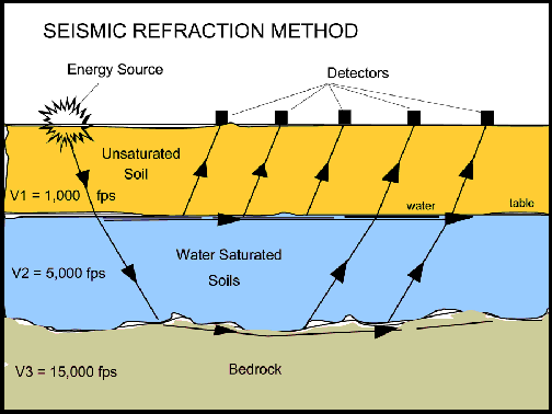
A seismic survey provides information on shallow lithology along the surveyed lines and produces soil-rock profiles. The method depends on seismic waves travelling at different velocities through different soils and rocks, and refracting as they cross the boundary between one type or condition and another. From that you get general soil types and the approximate depth to strata boundaries or to bedrock.
Electrical resistivity
Current finds the weak zone.
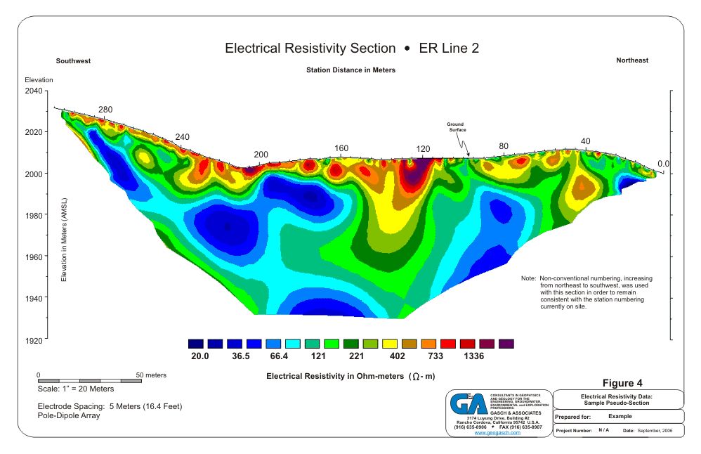
Resistivity imaging determines and estimates the overburden, the rock line and low-resistivity zones beneath the surface along the survey profile. We use the electrical current property to assess the character of subsurface material, on the principle that electric current will always pass through the weak zone.
Applications
What it is used for
- Rock competence for engineering applications
- Depth to bedrock
- Groundwater exploration
- Correction of lateral, near-surface variations in seismic reflection surveys
- Crystal structure and tectonics
Related services
Next step
Get a method and a rate.
Send us the survey line or the area to be covered and we will scope the spread.